Fourier Domain Optical Coherence Tomography (OCT)
In time domain OCT the location of scatters in the sample is observed by generation of
interferometric fringes at the detector as the reference reflector position
is axially translated. In contrast, Fourier domain OCT required the
reference arm to be held fixed, and the optical path length difference
between sample and reference reflections is encoded by the frequency of the
interferometric fringes as a function of the source spectrum. Two
configurations have prevailed in Fourier domain systems: spectral domain
(SD) OCT uses a grating to spatially disperse the spectrum across an
array-type detector, and in swept source (SS) OCT a narrow band laser is
swept across a broad spectrum, encoding the spectrum as a function of time.

Regardless of whether the spectrum is sampled in time or in position across
an array detector, the frequency of the interferometric fringes as a
function of spectrum encodes the location of the scatterer, with increasing
frequency corresponding to larger optical path length mismatches. A common
mathematical tool for extracting the frequency content of a signal is the
Fourier transform, however, it must be remembered that the true Fourier
transform pair of distance is not wavelength (also units of distance), but
in fact wavenumber (with units of inverse distance).
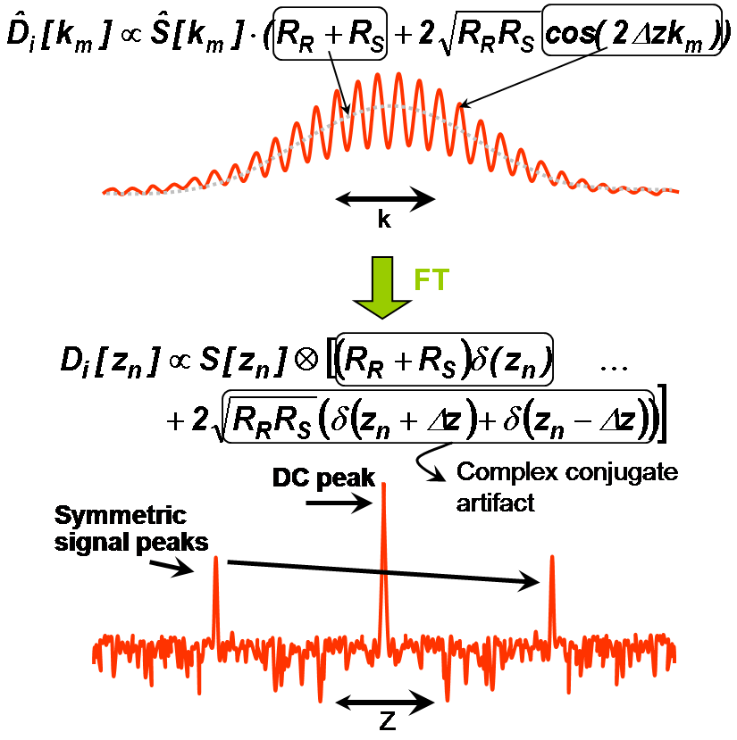
For the case of a single reflector in the sample arm, the equation for the spectral
interferogram can be written as in Eq. 1, analogous to the TD equation.

(1)
where the function is written in terms of wavenumber, k, and S(k) represents the intensity
profile of the source spectrum. The location of the reflector is revealed by
taking the Fourier transform of equation (1), generating equation (2):

(2)
where d(z) represents the Dirac delta function, and Ŝ(z) is
the Fourier transform of the source spectrum, of which the FWHM distance
represents axial resolution. Equation 2 contains three terms: the first term
is due to the non-interfering components of the sample and reference arms,
and represents a peak at zero path length mismatch (DC). The other two terms
represent the location the scatterer and its indistinguishable complex
conjugate image. The complex conjugate peak arises because the detector does
not measure the phase of the interferogram, which is required to uniquely
determine the location of the scatterer. This symmetry, referred to as the
complex conjugate artifact, reduces by half the usable depth range in FDOCT.