
Time-Domain Optical Coherence Tomography (OCT)
Optical coherence tomography (OCT) is an
emerging non-contact imaging modality for micrometer scale sub-surface
imaging of biological tissue.1 OCT has found its main application
in ophthalmic imaging, but this technology is also being used in small
animal imaging as well as imaging of embryonic structures in developmental
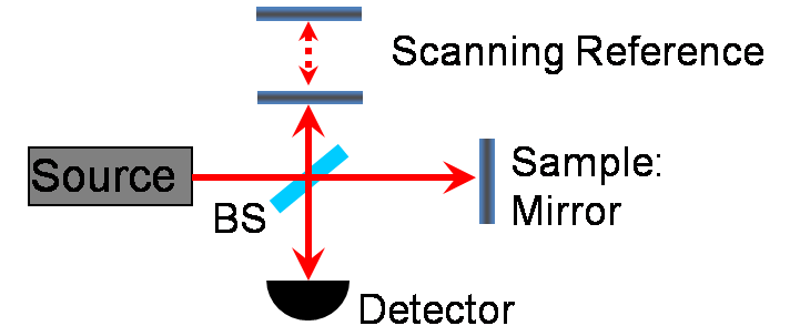
biology. A simplified optical setup for a fiber based OCT system utilizing a
low coherence source and a Michelson-type interferometer is illustrated in
Figure 1, below.
Cross sectional data along an axial line through the sample,
called an A-scan, is acquired by axially scanning the position of the
reference arm. Interference fringes are acquired at the photodiode detector
when the round trip distance from the sample reflection matches that of the
reference reflection. The magnitude of the observed fringes is proportional
to the reflectivity of the scatterer. A two dimensional profile, or B-scan,
is generated by scanning the interrogating beam laterally across the sample
and acquiring an axial scan at each lateral location. Subtle differences in
adjacent layers are visualized as differences in scattering intensities.
For the case of a point reflector
in the sample, i.e. a mirror, the extent of the fringes, representing the
axial resolution of the measurement, is determined by the coherence length
of the source spectrum,lc,
given by:
(1)
where lo is the center wavelength of the spectrum and dl
is the full width half max (FWHM) spectral bandwidth, assuming a Gaussian
spectral profile. In OCT, the axial resolution is thus decoupled from the
transverse resolution, which is dependent on the optical setup, in
particular on the numerical aperture of the objective lens.
Continuing with the case of a single reflector
in the sample, and for a system without dispersion, the photocurrent at the
detector, ID, can
be written as a function of Dx, the difference in reference
and sample reflection positions,

(2)
where Rs and Rr represent the
reflectivity of the sample and reference object, S(x) is the Fourier
transform of the source spectrum, and ko
is the center wavenumber of the source bandwidth. The first term on the
right hand side represents a DC offset due to non-interfering components,
and the second term describes the overlying interferometric fringes. The
reference arm power is typically much larger than the sample arm, and
determines the shot noise limit in the system sensitivity.